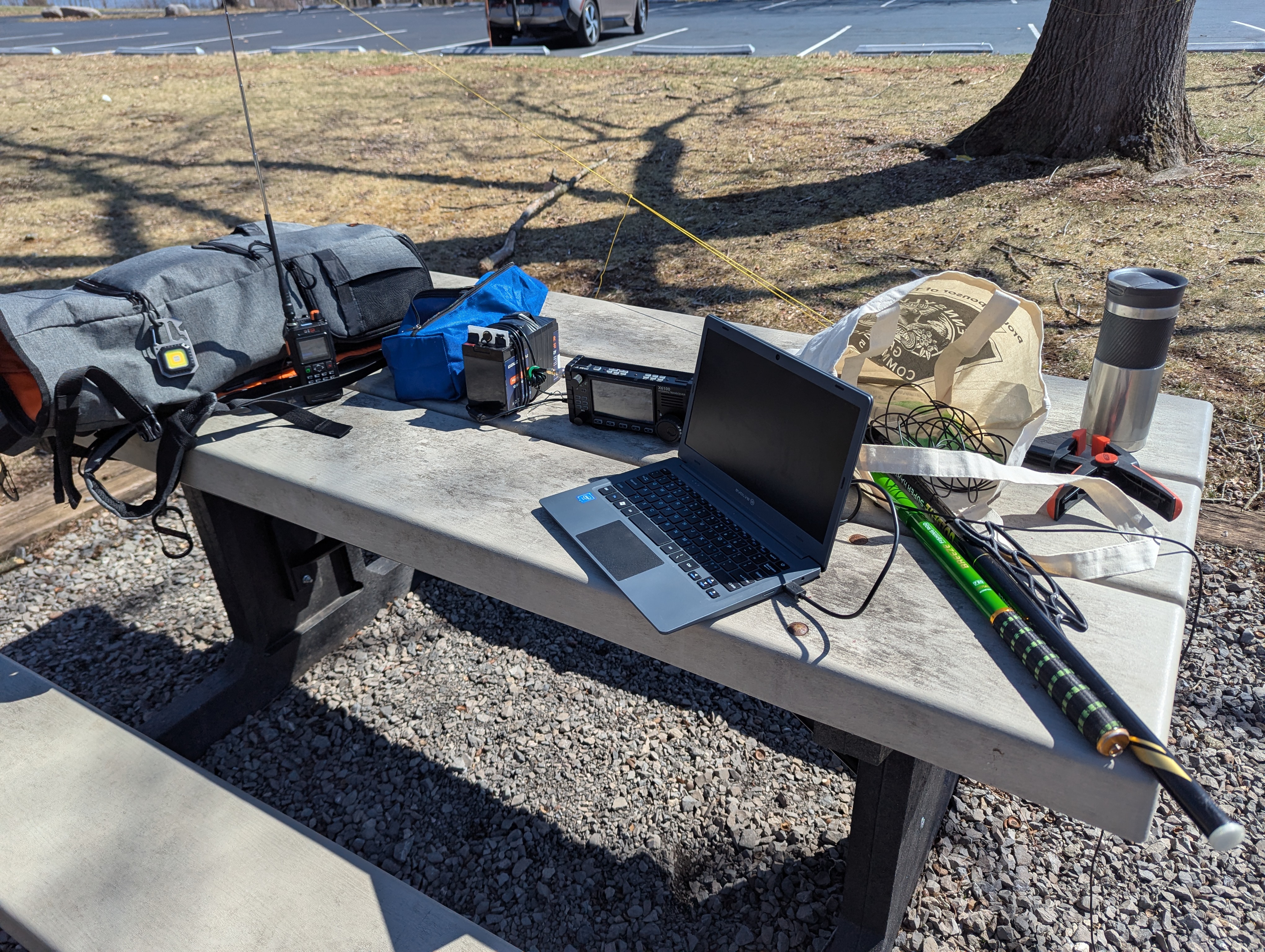
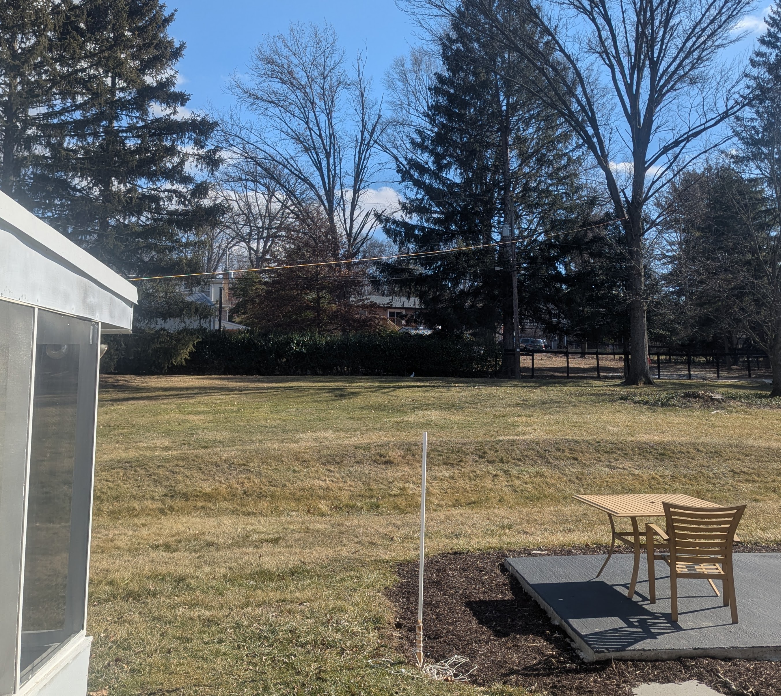
I was using the 71-foot (21.64m) EFRW antenna at home,
and I noticed SWR was surprisingly low as measured by the X6100
with the tuner disabled.
I suspected loss on the feed line,
but I also found this video
of another person
not using a tuner
with the same antenna.
I disconnected my feed line
at different places to find SWR jumps way high,
so the measurement is working:
- inside window
- outside window
- at the antenna
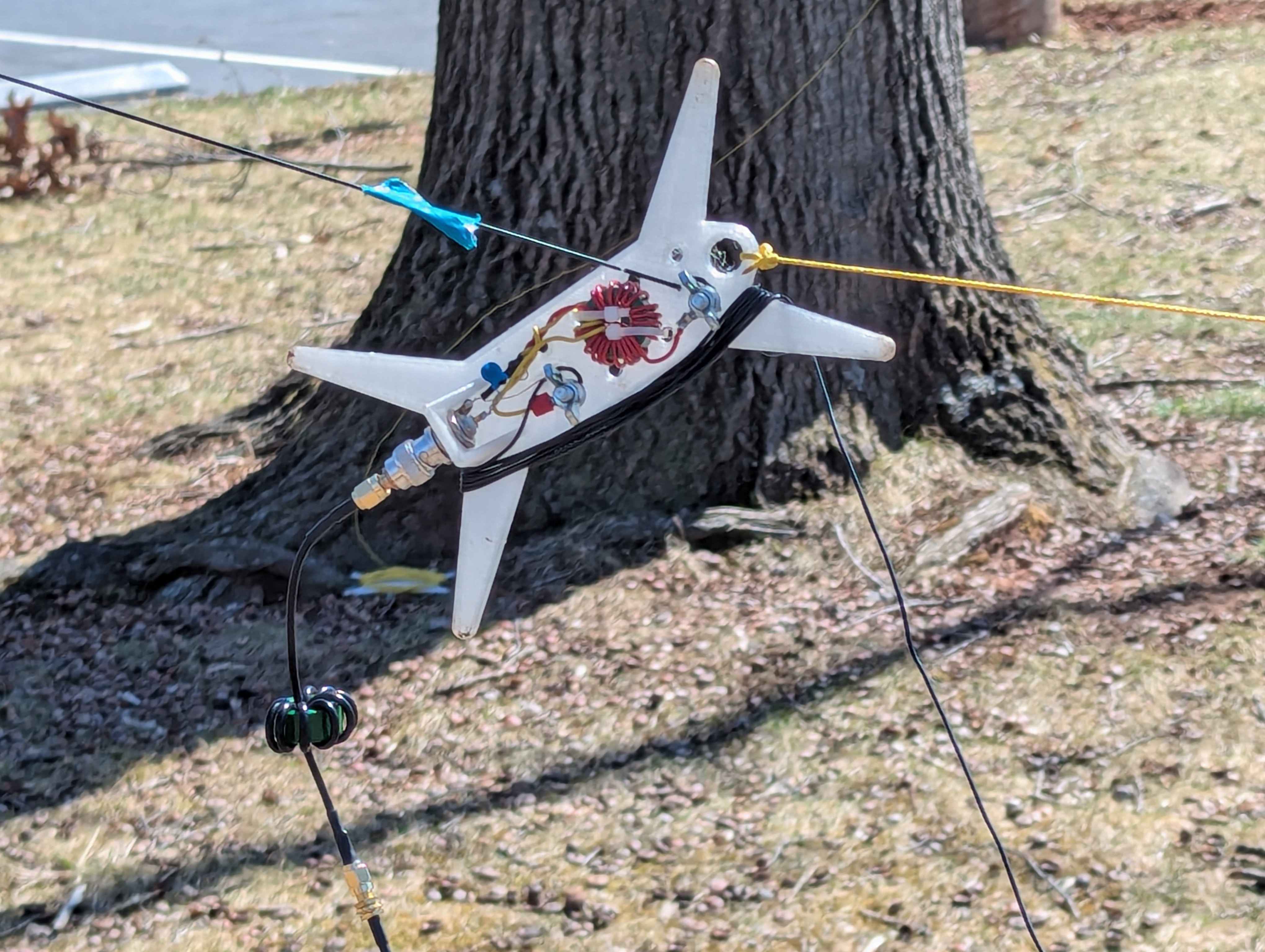
Does a very long wire have low SWR for everything?
Is the 9:1 giving low SWR?
The antenna’s working fine,
and FT8 shows far-flung signals like always.
Disconnecting antenna wire raised SWR above 1.5:1,
but not much.
Even with wires disconnected from the balun,
it’s receiving a very few FT8 signals on 10m,
and I can still transmit,
but it’s folding back power with SWR just below 2.
The tuner is definitely needed for 6m.